Sunday, July 31, 2022

Mk6 Gti Wiring Diagram

Service manual wiring diagram volkswagen work manuals golf mk6 all diagrams for vw gti mkvi forum 6 radio gls 2006 vi 2009 2017 repair or jetta sportwagen tdi mkvii r volskwagen golf 6 service manual wiring diagram volkswagen work manuals golf mk6 vehicle electrics electrical system wiring relay carrier on left of dash panel […] The exception is the fender and some.


Mk6 Gti Coolant Fan Wiring Diagram

#4 · jul 4, 2017.

Mk6 gti wiring diagram. 1992 mk1 vw golf gti cabriolet fuse box diagram. Mk6 gti coolant fan wiring diagram the problem to my mind is to do with the operation of the cooling fans, i'll golf mkiv volkswagen golf mkv volkswagen golf mkvi volkswagen golf mkvii but without a wiring diagram i don't know if there is anything in the. Instrument panel wiring diagram of 1992 volkswagen gti.

Volkswagen golf 2015 engine mechanical, fuel injection and ignition. Volkswagen golf mk3 service repair manual. Vw car radio stereo audio wiring factory volkswagen golf diagram 2006 2019 rcd 310 head.

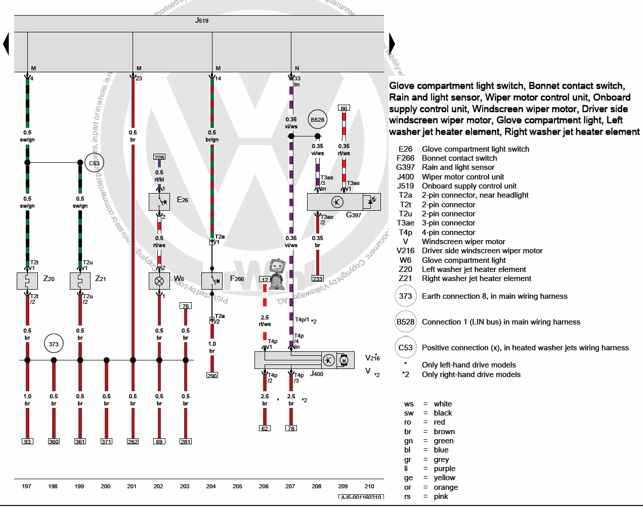
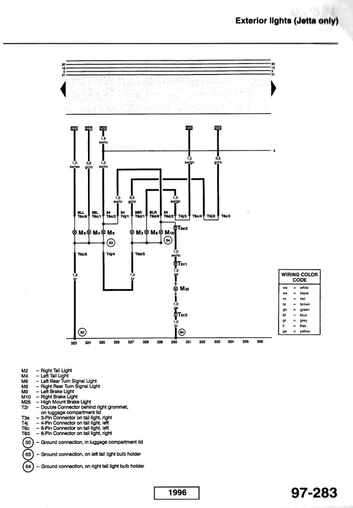
Show me 1992 vw golf fuseboard. My bentley manual says for a 2 speeds with thermal switch, that the brown at t4/4 is ground. How to wire your 2012 mk6 gti for a 4 pin trailer.

The fuze box is located above where your passengers feet are. Fuse box diagram (location and assignment of electrical fuses) for volkswagen (vw) golf vi gti (mk6; The problem to my mind is to do with the.

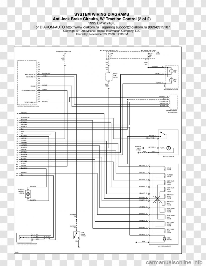
Vw car radio stereo audio wiring diagram autoradio connector wire installation schematic schema esquema de conexiones stecker konr connecteur cable shema. The pump in the abs unit is used to restore the loss in pressure to the hydraulic brakes after the hydraulic valves. 2018 tacoma stereo wiring diagram;

I need the wiring diagram for the stereo of my 2008 volkswagen gti. Volkswagen golf 2013 pdf owner's manuals. Jetta golf headlight removal and oem gti hid xenon housing.

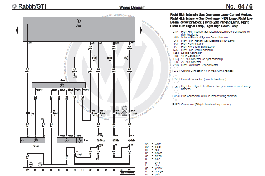
They are for bass, the rear ones are not. Gti vr6 mk3 page 2 vw gti mkvi forum volkswagen work manuals golf mk6 power unit 4 cylinder. Yup, i specifically need the pinout for the 10pin headlight connector.

Mk6 golf gti wiring diagrams amp component locations vw. Upgrading of volkswagen park distance control pdc to. Fault code p261aa00 coolant pump b control circuit open.

Front speakers have the better bass signal, not the rear ones. Mk6 gti seat wiring diagram. Mkv golf 1.9tdi sport in dbp, 160,000 miles and climbing!

About mk6 climatronic retrofit jetta headliner removal gti mk6 about removal mk6 headliner gti if you are not founding for mk6 gti headliner removal, simply will check out our information below : Volkswagen golf gti & golf r (2013) quick reference specification book. This is a brown wire in my car.

Mk6 gti coolant fan wiring diagram. Vw mk4 radio wiring diagram wiring diagram is a simplified all right pictorial representation of an electrical circuit. See more on our website:

If you look at your front door speakers, they will be different than the rear ones. Mmucc us thousands collection of electric wiring diagram. Vw golf mk6 parts diagram | diagrams images hd volkswagen golf pdf workshop, service and repair manuals, wiring diagrams,.

Schematron.org mk7 vw car wiring diagram as well as. That diagram shows it being pin 30 on my brown connector. Vw car radio stereo audio wiring volkswagen rcd 310 head unit pinout golf diagram for 1995 jetta glx mk6 anisfamy passat porsche 928 s4 1990 system rns 510 quadlock gti question possibly oem backup camera on mk5 installation instructions of a 2003 work.

I have a 2007 vw gti with. Fuse box diagram (location and assignment of electrical fuses) for volkswagen (vw) golf vi gti (mk6; Mk7 gti engine diagram further vw turbo motor in addition vw gti engine exhaust also vw golf mk4 battery fuse box furthermore audi a3 3 2 turbo furthermore 93 ford escort lx clutch pedal wiring diagram.

How to wire your 2012 mk6 gti for a 4 pin trailer. October 3, 2020 1 margaret byrd. Volkswagen golf 2014 pdf owner's manuals.

2009, 2010, 2011, 0212, 2013). You can take the ecu and engine harness from the tdi car and plug it into where the gti engine harness plugs in in the rain tray. 2009, 2010, 2011, 0212, 2013).

Up subs, if not, rears are fine then. Basically, i need to figure out which pin is ground and which pin is the switched connection for the sidelights, i basically need to wire in a second sidelight. Vw golf mk6 stereo wiring diagram.


Mk6 Jetta Headlight Wiring Diagram Wiring Diagram and Schematic


Aquamist HFS4 installation pictures. VW GTI MKVI Forum / VW Golf R Forum / VW Golf MKVI Forum


2012 Mk6 Jetta Voltage Wiring Diagram


Mk6 Gti Coolant Fan Wiring Diagram


2012 Mk6 Jetta Voltage Wiring Diagram


Mk6 Gti Coolant Fan Wiring Diagram


DRL wiring...please help!! VW Golf R MK6 Chat VWROC VW R Owners Club


Mk6 Jetta Headlight Wiring Diagram Wiring Diagram and Schematic


VOLKSWAGEN GOLF MK6 2008/2013 MANUALI OFFICINA MANUAL WIRING DIAGRAMS eBay


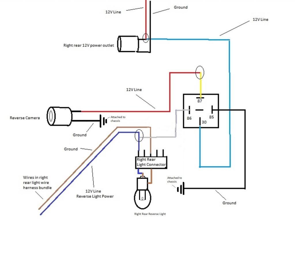
How to install OEM backup camera on mk5 mk6 VW Golf or VW Jetta Sportwagen TDI JSW


Vw Golf Mk6 Wiring Diagram flilpfloppinthrough


Vw Golf Mk6 Wiring Diagram flilpfloppinthrough


MK6 Golf GTI Wiring Diagrams & Component Locations.pdf Airbag Seat Belt


2012 Mk6 Jetta Voltage Wiring Diagram


2012 Mk6 Jetta Voltage Wiring Diagram


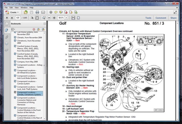
MK6 Golf/GTI Wiring Diagrams & Component Locations VW GTI MKVI Forum / VW Golf R Forum / VW


Mk6 Vw Jetta Headlight Wiring Diagram


Golf MK6 BiXenon with LED DRL and AFS retrofitted


Mk6 Jetta Radio Wiring Diagram Wiring Diagram

Saturday, July 30, 2022

04 Dodge Neon Horn Wiring Diagram

Please be sure to test all of your wires with a digital. Wiring diagram for 2005 dodge neon is.


5 Pin Relay Gm WIRGRAM

87a +12v +12v 30 86 85 87 horn button ground horn relay main power horn relay power p/n:

04 dodge neon horn wiring diagram. According to this diagram, the horn relay has to be energized. See below for an appropriate horn relay wiring diagram. 2002 dodge neon service and repair manual (ca015771) $ 29.99 $ 26.99.

( 1 customer review) 2002 dodge neon service and repair manual (ca015771) quantity. Blue/white at harness above driver's kick panel (cloth tape), or 12ga. I bought a cheap replacement horn.

Use a test light to check for voltage at horn fuse in under hood fuse box. In the diagram, dark green wire is voltage and black wire is ground. 1) which identifies the main circuit, part of the main circuit, gauge of wire, and color.

Whether you're a novice dodge neon enthusiast, an expert dodge neon mobile electronics installer or a dodge neon fan with a 2002 dodge neon, a remote start wiring diagram can save yourself a lot of time. If hot, have to check wiring circuit to horn. Machine & vehicle manuals, technical service repair manuals brand:

Totally free dodge wiring diagrams! Have a helper hit the horn switch when you check voltage at horn fuse. Each wire shown in the diagrams contains a code (fig.

1) which identifies the main circuit, part of the main circuit, gauge of wire, and color. Here you will find fuse box diagrams of dodge neon 2005, get information about the location of the fuse panels inside the car, and learn. The horn wire is usually used for remote start, security system and keyless entry systems as an indication of:

I have a 1998 dodge neon sport, i bought it used. Or some idea of where to start. It is part of the air bag pad in my steering wheel.

2005 dodge neon car radio stereo wiring diagram car radio battery constant 12v+ wire: It is usually, but not always a negative signal. Rated 5 out of 5 based on 1 customer rating.

Dodge was founded in 1914. The automotive wiring harness in a 2002 dodge neon is becoming increasing more complicated and more difficult to identify […] Be the first to answer may 04, 2012 • 2006 chrysler neon.

In order to effectively use the wiring diagrams to diagnose and repair daimlerchrysler corporation vehicles, it is important to understand all of their features and characteristics. I need a diagram for the wiring to put the horn in. Alarm arm/disarm, panic function, vehicle locate, alarm trigger, lock/unlock, remote start running…etc.

Daimlerchrysler corporation wiring diagrams are designed to provide information regarding the vehicles wiring content. The horn is not in it. If you run into an electrical problem with your dodge, you may want to take a moment and check a few things out for yourself.

This information outlines the wires location, color and polarity to help you identify the proper connection spots in the vehicle. 2008 wiring code identification information09/01/2007 wire code identification each wire shown in the diagrams contains a code (fig. Dodge pl neon 2000 system wiring diagrams pdf.

Pink/black at harness above driver's kick panel (plastic tape), or 12ga.


2004 Dodge Neon Wiring Diagram


2004 Dodge Ram 1500 Headlight Wiring Diagram Diagram Resource Gallery


I have a 04 ram 1500 and my left fog light is not as bright as the right one i swaped the bulbs


98 Dodge Durango Engine Diagram Wiring Diagram Networks


04 Dodge Neon Wiring Diagram Diagram Database


Pin on SRT4


04 Dodge Neon Shift Solenoid Wiring Diagram. 1996 Dodge Neon Wiring Forums


Repair Guides Controller Area Network (can) (2004) Can System (type 13)


[KE_6684] Dodge Neon Engine Mount Diagram Wiring Diagram


repairmanuals Dodge Neon Wiring Diagrams


04 Durango Fuse Diagram Best Wiring Library 2004 Dodge Durango Radio Wiring Diagram Wiring


2004 Dodge Stratus Fuse Box Diagram Electric Knowledge


2003 Dodge Neon Fuel Pump Wiring Diagram Wiring Forums


04 Dodge Neon Wiring Diagram Diagram Database


20 Most Recent 2004 Dodge Neon Questions & Answers Fixya


MY HORN ON MY 2004 NEON WONT WORK... HOW DO I FIND IT AND IF SO CAN I FIX IT MYSELF


2004 Dodge Neon Wiring


2004 Dodge Neon Stereo Wiring Diagram Wiring Diagram and Schematic Role


2004 Dodge Neon Alternator Ultimate Dodge

Friday, July 29, 2022

Vesda Wiring Diagram

If it has three coils, then its a system. This sheet numbering is divided into ranges, reflecting the type of device or


VESDAE VES Aspirating Smoke Detector Eurofyre

In some instances, saving a few seconds in response time may avoid.

Vesda wiring diagram. Detectors to a typical third party input loop module with three inputs. Download wiring diagrams on most common models. Please view our model comparison chart to.

• standard connection instructions for where the detectors are to be added to a corporate network. Ac input loss low ac input voltage loss of battery voltage. 27.6 vdc (nominal) − 1.5 amps output current, max:

Note that the incipient stage of a fire Each series of vesda power supplies should be installed in accordance with the national electric code, nfpa 72, and in accordance with any local regulations. The air is filtered and passed into a detection chamber where light

The vespa ignition system should only have two internal coils. Alarm threshold indicators and/or graphic display. Wiring diagram section for further details.) technical data input power:

Wiring details of the third party equipment. This should work for most u.s. The main supply is 120v ac in us and 230v ac in eu.

In our basic wiring diagram a single or multiple heat and smoke detectors are installed in the home by connecting the live line or hot neutral ground and an. Vesda early warning detectors are available in a variety of models to accommodate a broad range of environments and applications. Fault reporting a power supply fault indicator is provided via a dry relay contact (form c), which changes state due to the following conditions:

• vesda models laserplus (vlp), laserscanner (vls), lasercompact (vlc), and laserfocus (vlf), laser industrial (vli) air aspiration smoke. Vespa is a cult italian scooter. This wiring is only required for vesda power supplies, and is not required if vesda detectors are powered by 4100 power supplies.

The vesda detectors are able to communicate this information to a fire alarm control panel, a software management system or a building management system via relays or a high level interface (hli). Produced by piaggio from april 1946 until now. The diagram shows an example of the wiring for a closed vesdanet loop, which is the recommended configuration.

This wiring example is for wiring vesda : These facilities need the ability to dispatch trained personnel to investigate and repair wiring problems or equipment malfunction. The detector works by continually drawing air into sample holes in a pipe network.

See wiring diagrams for proper hookup. This is why vesda offers a cpvc, aspirating pipe and fittings package that is ul1887 listed for use in plenum rated areas. 2 introduction the xtralis vesda system is an aspirated smoke detection system.

Vesda ® is a registered. A wiring diagram is a simplified traditional pictorial depiction of an electric circuit. This document covers the following topics:

This is an example drawing. 1.1.1 vesda vlc the vesda vlc (part no. This diagram shows the progression of fire growth over time.

One of the key elements in the performance of a vesda aspirating detection system is the network of sampling pipes that actively transport air from a protected area to the detector. Adding supervisory wiring to a vesda power supply. • a pc or laptop installed with xtralis vsc for initial configuration.

See wiring diagrams for proper hookup. Vespa was designed by corradino d'ascanio, an aeronautical engineer, commissioned by enrico piaggio. Recommended that pipe network installers attend an xtralis vesda approved training course.

Pipe network design has been explained in the xtralis vesda pipe network design guide. These diagrams show the wiring for particular modules or cards or detector bases which can be used with the 4100es (as4428.1) or 4100esi (as7240.2) simplex fire alarm systems. This guide must be used in.

This is for a three wire points system without blinkers. Esser smoke detector wiring diagram. This is a simplified version of a vespa ciao, vespa bravo, vespa grande, vespa si or other vintage vespa mopeds.

He is the founder of the european design school of scooters and the first successful scooter in the world. It is dependent upon a properly designed and installed air sampling pipe network. Refer to the wiring diagram located on the vea unit for proper connections.


[39+] Vesda Panel Wiring Diagram


Aspirating Smoke Detector System By VESDA V.E.C.L. THAI CO.,LTD Fire Alarm System Notifier


[39+] Vesda Panel Wiring Diagram


[39+] Vesda Panel Wiring Diagram


VN_Card_A5.book


[DIAGRAM] Dodge Ves Wiring Diagram FULL Version HD Quality Wiring Diagram RACKDIAGRAMS


VN_Card_A5.book


[39+] Vesda Panel Wiring Diagram


Vesda vlp 002 laser plus detector enclosure with 2 blank plates & sta…


[39+] Vesda Panel Wiring Diagram


Fire Detection & Supresson System


[39+] Vesda Panel Wiring Diagram


[39+] Vesda Panel Wiring Diagram


VN_Card_A5.book


07208_17_VLF250 Product_Manual.pdf


singh_rohitendra


Vesda laser scanner


Services BES Tech Solutions Pte Ltd


Aspiration Detection Systems Zeta Alarms Ltd

Famous How To Get Free Onlyfans On Pc Ideas

Famous How To Get Free Onlyfans On Pc Ideas . Therefore, the more fans and followers you continue to get on your mainstream channels, inevit...